General
Engine/transmission, removing
Note! As the illustrations in this service information are used for different model years and / or models, some variation may occur. However, the essential information in the illustrations is always correct.
SafetyCaution! FIRE RISK. Take great care to avoid causing sparks when working on the fuel system. |
Preparation | |
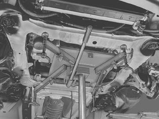
 | Remove:-the battery negative lead. First read Note when disconnecting/connecting the battery lead -the engine stabilizer brace between the suspension turrets -the engine cover by pulling it straight up -the air cleaner (ACL) assembly. Seal the opening in the pipe for the turbocharger (TC) -the connector from the solenoid valve on the air filter cover -the charge air hoses between the engine and charge air cooler. Seal the openings -the cover over the central electrical unit -the connector for the engine cable harness from the central electrical unit -the positive lead for the starter motor from the terminal block. |
Removing components on the left-hand side | |
 | Remove:-the ground terminal in the wheel arch -the servo hose from the vacuum pump -the connector for the engine coolant heater. Separate the clutch cable and remove the transmission cables. See Transmission, removing . Tie up the cable(s) to the central electrical unit. Disconnect the connector for the backup lamp sensor. |
Removing the control module | |
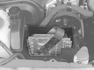 | Remove:-the cover over the control modules -the control modules. Use tool 999 5722 . Also see Engine control module (ECM), replacing . Separate the control module box. Disconnect the engine cable harness. Also see Central electrical unit, engine compartment, replacing . Caution! Do not touch the terminal pins on the control module with fingers. Static electricity may damage components in the control module. Remove the ground terminal for the engine cable harness at the right wheel arch. |
Removing the engine cooling fan (FC)Remove the engine cooling fan (FC). See Engine cooling fan (FC), replacing . Install radiator protection 999 5474 . |
Draining coolantPosition a container under the radiator drain cock. Drain the coolant. Caution! Avoid skin contact with the coolant. Close the cock. |
Separating the front exhaust pipe | |
 | Remove:-the screw for the front exhaust pipe and support bracket -the three nuts that hold the front exhaust pipe to the turbocharger (TC). Tie up the front exhaust pipe at the right suspension turret. |
Removing components on the right-hand side | |
 | Remove:-the upper radiator hose -the hoses for the heater unit at the terminal in the firewall -the radiator breather tube by the expansion tank -the ABS line and clips and the power steering hose. Disconnect the connector for the level sensor in the expansion tank. Lift up the power steering fluid reservoir and the expansion tank. Place them on top of engine. |
Exposing the air conditioning (A/C) compressor | |
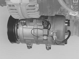 | Remove the auxiliaries belt. Disconnect the one-pin connector for the compressor magnetic clutch. Remove the four screws holding the air conditioning (A/C) compressor to the engine. Tie up the compressor in the front cover plate. Caution! Handle the compressor carefully. Ensure that there are no kinks in the air conditioning (A/C) pipes. |
Removing componentsRaise the car. Remove:-the left and right front wheels -the splash guard under the radiator -the splash guard under the engine -the lower radiator hose. |
Cars with engine block heaters (option) | |
 | Drill out the first three blind rivets at the right mounting for the fender lining to the fender edge, seen from the front edge and upwards. Move the fender liner to one side. Disconnect the connector for the engine block heater. Remove the nut from the upper mounting bracket for the heater. Remove the fuel line from the clip. |
Disconnecting the connectorDisconnect the connector from the pressostat in the air conditioning (A/C) receiver drier. Slacken off the lower right screw for the cooling unit. Pull the cooling unit down. Carefully pull the wiring for the pressostat through the cavity at the mounting for the cooling unit. Release the lower ventilation pipe for the control module box from the sub-frame. |
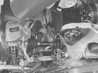
Preparations for removal of the drive shafts | |
 | Remove on the left and right-hand sides:-the tie rod from the wheel spindle -the link rod from the anti-roll bar -the sound insulation cover for the drive shaft -the nut holding the control arm to the ball joint -the center screw from the end of the drive shaft. |
Separating the fuel lineNote! Use paper to collect any spilled fuel. Separate the quick-release connectors for the fuel lines to the engine and engine block heater (option). See also: Fuel system, quick-release connectors . |
Separating the steering shaft | |
 | Remove the ignition key. Remove the screw from the joint between the steering gear and the steering shaft. |
 | On one side, measure the length of the tie rod in relation to the steering gear housing. Note the measurement. Press up the joint from the steering gear. Caution! The steering shaft must not be turned. The contact reel in the SRS system could be damaged. |
Lowering the engine and transmission | |
 | Use a post hoist with a lifting table and stud guides. Position the lifting table against the sub-frame. Note! Ensure that the lifting table is centered under the sub-frame for optimal weight distribution. Check that the lifting table is correctly applied against the sub-frame. |
 | Remove:-the screws for the sub-frame brackets -the screws for the sub-frame. Lower the engine and transmission approximately 15 cm so that the drive shafts describe a horizontal line between the hub and transmission. Caution! Ensure that no hoses, wiring or anything else catch in the engine and transmission unit when it is lowered. Unhook the control arms from the ball joint pinion. Hold the constant velocity joint. Pull the drive shaft off the hub. Let the drive shafts rest against the control arms. Turn the engine block heater out of its position. Check that the air conditioning (A/C) compressor is hanging free. Continue lowering the engine and transmission unit. |
Engine/transmission, installing
Note! As the illustrations in this service information are used for different model years and / or models, some variation may occur. However, the essential information in the illustrations is always correct.
Hint: For tightening torques not in the text, see also Tightening torque .
Installing the engine and transmission unitRaise the engine and the transmission unit. Use a lifting table with locating pins. Stop when the sub-frame is approximately 15 cm below the frame members. | |
 | Install (left and right-hand sides)-the drive shaft to the hub. Install the center screws. Do not tighten yet! -the ball joint to the control arm. Install the nuts. Do not tighten yet! Caution! Ensure that the mating surfaces on the ball joints and control arms are clean. Twist the engine block heater (option) into position. Check that the air conditioning (A/C) compressor is correctly positioned. Check that the tie rod is in the correct position. Check that the transmission cable is routed between the steering shaft and the firewall. Align the steering shaft joint on the steering gear. Lift the engine and transmission unit up to the frame members. Caution! Ensure that no hoses, wiring or anything else catches. |
 | Install:-a new screw in the steering shaft joint. Tighten to 20 Nm -new screws in the sub-frame. Lubricate the screws -the washers at the front edge and the support plates at the rear edge of the sub-frame. Tighten the screws for the sub-frame. Tighten to 105 Nm. Angle-tighten 120°. Use bevel protractor 951 2050 . Start on the left hand side of the sub-frame. Continue with the right hand side. Tighten the screws for the brackets at the rear of the sub-frame. Tighten to 50 Nm. Remove the lifting table. |
Connecting fuel linesWhen assembling the fuel lines, see also: Fuel system, quick-release connectors . Connect the quick-release connector and the fuel line to:-the engine -the engine block heater (option). Use lubricant 1161580. |
Installing components | |
 | Install:-the heater fuel line in the clips (option) -the connector on the pressostat in the air conditioning (A/C) receiver drier. Screw the cooling system into place -the lower ventilation pipe for the control module box in the sub-frame -the nut for the upper mounting bracket for the heater -the lower radiator hose -the splash guard under the radiator. |
Assembling the spring strut | |
| Tightening Tighten:-the nut ball joint/control arm. See: Tightening torque . Counterhold using Tx40 -the center screw in the drive shaft. Tighten to 50 Nm. Install:-the sound insulation cover for the drive shaft -the tie rods. Use new nuts. Tighten to 70 Nm -the link rod to the anti-roll bar. Use new nuts. Tighten to 50 Nm. Counterhold with Tx27. |
Cars with engine block heaters (option) | |
| Connect the heater connector to the cable harness. Ensure that the connector and cable harness are secured to the body. Rivet the fender liner to the fender edge. Check that the quick-release fuel line connector is secure at the engine block heater. Install the front wheels. See Installing wheels . |
Installing the air conditioning (A/C) compressor | |
| Install the four screws whilst the compressor is loose. Raise the compressor and screw it into place. Caution! Handle the compressor carefully. Ensure that there are no kinks in the air conditioning (A/C) pipes. Connect the one-pin connector to the compressor magnetic clutch. Install the auxiliaries belt. |
Installing componentsConnect the cable harness to the control module box. See Central electrical unit, engine compartment, replacing . Install:-the ground lead to the ground terminal at the right fender edge in the engine compartment -the intermediate piece for the control module box -the control modules. See Engine control module (ECM), replacing -the cover for the control module box -expansion tank. Connect the radiator breather tube to the expansion tank. Tighten the clamp. Connect the connector for the level sensor in the expansion tank -servo oil reservoir. Check that the hoses are correctly positioned. Clamp the ABS cable to the servo hose. |
Installing the front exhaust pipe | |
| Install:-the screw for the front exhaust pipe and support bracket -the three nuts that hold the front exhaust pipe to the turbocharger (TC). Lubricate the studs on the turbocharger (TC). Use paste 116 1408. Warning! Avoid skin contact with the paste. |
Installing componentsInstall:-the engine coolant hoses to the heater unit -the servo hose on the vacuum pump -the ground terminal in the wheel arch. |
Installing the transmission cableInstall the transmission cable. Assemble the clutch cable. See Transmission, installing . Connect the connector to the back-up lamp. |
Installing the engine cooling fan (FC)Remove radiator protection 999 5474 . Install the engine cooling fan (FC). See Engine cooling fan (FC), replacing . |
Installing the air cleaner (ACL) housing | |
 | Install:-the air cleaner (ACL) housing assembly -the hose to the fresh air intake for the turbocharger (TC) -the air cleaner (ACL) housing, fresh air intake, solenoid valve and cable harness in the clips on the air cleaner (ACL) housing -the connector on the mass air flow (MAF) sensor -the connector and positive power supply in the central electrical unit -the cover for the central electrical unit. |
FinishingInstall:-the engine cover -the engine stabilizer brace between the suspension turrets -a new tie strap for the servo hose -the cable to the battery negative terminal. First read Note when disconnecting/connecting the battery lead . Top up the coolant. Function testRun the engine at fast idle speed until the thermostat opens. Ensure that the heater control in the passenger compartment is at the maximum position. Check the engine for leaks. Top up the coolant if necessary. Install the engine cover. |